Aspire
Aspire tarjoaa tehokkaan mutta intuitiivisen ohjelmistoratkaisun osien luomiseen ja leikkaamiseen CNC-jyrsimellä. On olemassa työkaluja 2D-työstöratojen 2D-suunnitteluun ja laskemiseen, kuten profilointiin, taskuintiin ja poraukseen, sekä 2,5D-työstöratoja, mukaan lukien; V-veisto, prismaveisto, muovaustyöstöradat, aallotus, viistotyöstörata ja jopa koristeellinen teksturointistrategia.
Premium-pakettimme tekee Aspiresta lisätyt 3D-suunnittelutyökalut, joiden avulla voit luoda omia 3D-kohokuvamalleja ja työstää niitä 3D-työstöstrategioilla. Aspiren ainutlaatuiset 3D-mallinnustyökalut yhdistettynä kattavaan 2D-suunnittelu- ja muokkaustyökalusarjaan tekevät omien 2D- ja 3D-osien luomisesta helppoa alusta alkaen sekä mahdollisuuden tuoda ja muokata ulkoisia 2D- ja 3D-tietoja.
Comprehensive Set of 3D Modeling Tools
Enable you to explore your creativity and create your own relief models for 3D machining.
Extensive set of Model Editing Tools
An extensive set of editing tools to help you manipulate 3D data.
Interactive Model Sculpting Mode
Powerful sculpting tools mean models can be manipulated like a virtual piece of clay.
$5000+ Worth of Free Clipart
Includes 2D and 3D Clipart that can be used in your own projects or edited to create new variations.
Job & Material Setup
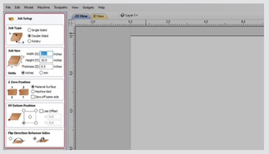
In the Job Setup dialog, you can pick whether you want to create a single-sided, double-sided or a rotary job. You can change that, retrospectively.
Define how you want to flip the material for double-sided projects from the Job Setup dialog. This influences the positioning of the vectors and models so that geometry on each side is created in the appropriate positions relative to the opposite side.

Multi-Sided View
You can view the opposite side’s geometry using the keyboard shortcut ‘=’, or through the ‘View’ menu.
In the 2D view, you will see the opposite side’s vectors as if you were looking at them through the material block.
In the 3D view, you will see the entire merged model as if it was simulated.

Importing STL Model
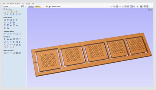
When importing an STL model (with the ‘Import both Sides’ option enabled) into a double-sided project, each side of the model will go onto a side.
You can import the entire model on each side by sliding the slicing plane all the way to the bottom. This is useful when importing models which contain non-convex surfaces, such as, a plate.

Machine Wrapped Rotary Parts
Enables the use of a rotary axis (also called a 4th axis or indexer).
Wrapped Rotary Machining
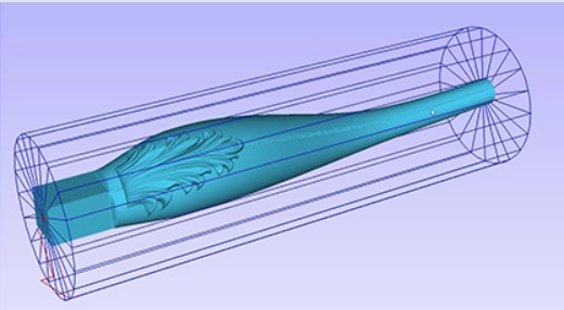
Enables the use of a rotary axis (also called a 4th axis or indexer). Where you can create rotary projects and visualize your job in a wrapped environment, with the ability to create and simulate the toolpaths in an auto - wrapped simulation.
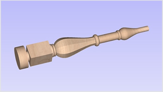

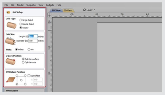
Rotary Job and Material Setup
In the Job Setup dialog, you can pick whether you want to create a single-sided, double-sided job or a rotary job. You can change that, retrospectively.
Define your cylinder dimensions, the orientation of the job, how the 2D view will be laid out, and which axis we're wrapping around.

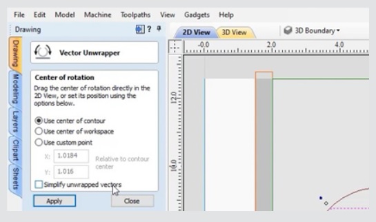
Vector Unwrapping
The vector unwrapper tool converts a vector into another vector suitable for using with the two-rail sweep tool to create rotary models from a desired cross section.
This is useful when rather than modeling a profile along the rotation axis, it is more intuitive to specify a desired cross section. The tool transforms a vector, representing a cross section, into a profile vector that can be subsequently used with two rail sweep tool.

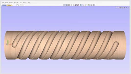
Spiral Toolpaths
In order to create a toolpath that wraps around multiple times, one can create a long vector at a certain angle. Such a vector is an equivalent to the strip of fabric when it is unwrapped from the roll.
Although such a toolpath will exceed the 2D workspace of the rotary job, thanks to the wrapping process during both simulation and machining the toolpath will actually stay within material boundaries.

Model Import into Rotary Project
The software has the ability to import full 3D models from third party software for unwrapping in a rotary job, where you can position and orient the model in a rotary view.
Not only can you import full 3D models for unwrapping the software also allows for the importing of "Flat 3D" models (relief style models) that you can position and simulate before cutting.

Drawing & Layout Tools
The software has a comprehensive set of drawing tools to let you easily create vectors from scratch or add to imported data.
Vector Shape Creation
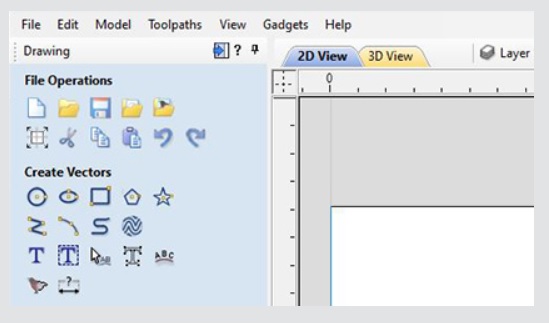
The software has a comprehensive set of drawing tools to let you easily create vectors from scratch or add to imported data. These include options for creating standard shapes (circle, elipse, rectangle, polygon and star) along with line, curve and arc drawing tools. There is also a powerful tool to create vector textures for panels and backgrounds. These tools can be controlled using typed input to create exact sized objects or can be used dynamically with the mouse to sketch your artwork. The tools also take advantage of the 'snapping' to let you use points on existing objects to 'snap' onto when you are drawing vectors.

Picture Editing & Cropping
With the ability to import bitmaps into the software, you can further edit imported images using the 'Edit Picture' tool, this allows you to adjust the visual properties of a selected bitmap, enabling you to adjust the contrast, brightness and gamma of any selected image.
Borders of different sizes and radii can also be added to bitmaps for aesthetic purposes. Bitmaps can also be made black and white. The software also has the ability to crop images to any given vector allowing you to remove parts of the image you are not interested in.
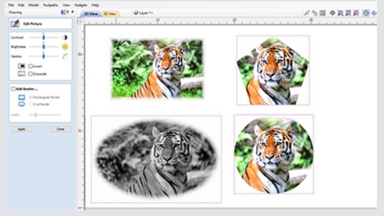

Image Tracing (Vectorization)
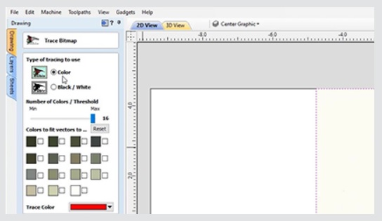
Image tracing also known as vectorization allows you to take an imported image such as a scanned drawing, graphic design or photo and to convert colors in that to vector outlines. These outlines can then be used as part of your design to create toolpaths or to generate 3D shapes using the modeling tools. The software will import many file formats including jpeg, bitmap, gif, png, tif, it will also extract images from a PDF file.

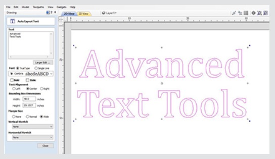
Advanced Text Tools
The 'advanced text' tools let you access true type or open type fonts on your PC to create text outlines for your design. In addition, the software comes with a selection of specialist single stroke / stick engraving fonts for efficient machining when making things like badges or small signs.
When creating text you are able to see live feedback of the text that you create and edit. The text can be controlled using automatic sizing and layout options. There is an inbuilt spell checker where errors will be underlined in red, where you are able to locate the correct spelling as well as having the ability to add words to the software’s dictionary too!
There are also editing tools for fitting text to a curve and interactive text arcing and spacing (kerning) where the text maintains formatting, allowing you to easily make edits after the text has been created. This text can be dragged dynamically along a curve so you can perfect the placement of your text.

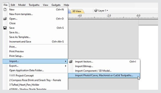
Import 2D Data (DXF, DWG, EPS, AI, SKP, SVG etc.)
Data can be imported from a huge range of other design programs using a variety of industry standard file formats. These include DXF, EPS, AI, SVG and SKP (SketchUp) as well as PDF files. Once imported, the program has a wide range of tools to make working with this data as efficient as possible.
A very important set of tools are those used to identify duplicate vectors and identify and rejoin open vectors. These tools can save an great deal of time when working with poor quality data to get it ready to machine.
As well as importing vectors from other programs the software also offers the ability to export your data in either DXF, EPS or AI file formats. This feature is very important if you need to share data with a customer in order that they can use it to plan a layout or installation.

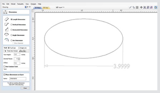
Basic Dimensioning
The dimensioning tools allows you to create a variety of different types of measurements on your drawing. These can be oriented in any direction or fixed horizontally or vertically. There are also options to add angular and arc dimensions. You can control the text height, font number of decimal places and position for each one. Dimensions can be snapped to vectors, guidelines and the corners or mid-points of each side of your work area.

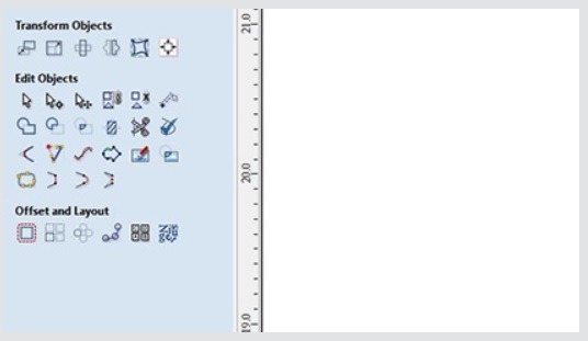
Vector Transform & Editing
Whether your design vectors have been created in the software or imported you have a large choice of editing options to prepare your part for toolpath creation or modeling. Vectors can be easily scaled, moved, mirrored, distorted, grouped, welded, trimmed, filleted, extended, offset, smoothed and joined together. As with the drawing tools you either have precise control over the editing values adjust the vectors very accurately or can use the mouse to dynamically make adjustments until your layout looks correct.

Vector Layout
In addition to the editing tools the software also has tools to let you layout parts either in a rectangular array to create a grid of objects or in a circular array to create symmetrical layouts around a center point. When laying out a grid you can adjust mirroring options and shift alternate rows and columns to make more complex layout patterns.
Vector shapes can also be pasted along the path of another vector by specifying the distance between each copy or just fitting a specific number on the guiding object.

True Shape Nesting
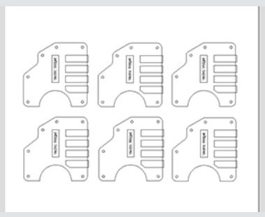
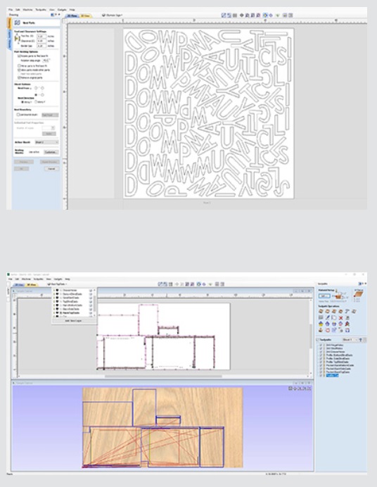
True Shape Nesting lets you automatically arrange and fit vector shapes and components into your material size or user definable area, to get optimal material usage and minimum wastage. Part Nesting is perfect for Sign and Cabinet makers who need to minimize material wastage and cut as many parts – letters & cabinet doors / panels – as possible from sheet materials.
Reduce Material Costs = Increased Profits
The nesting routine places vector shapes and/or components as close to each other as possible ensuring a sufficient gap to allow the parts to be cut out correctly. The nesting includes options to control part direction to reflect material grain or machine orientation. It intelligently determines what parts of your geometry should be nested together. It can also automatically nest objects on both sides of a job together to create two-sided nested geometry.

Aspire has many other good features and functions.
Watch more:
Ota yhteyttä
Ota yhteyttä ja kerro mitä lisätietoja haluat tästä tuotteesta
