Cut3D
Cut 3d on Cam-ohjelma, jolla tehdään g-koodi cnc-jyrsinkoneille 3d-malleista, jotka on suunniteltu 3d cad-ohjelmalla kuten AutoCAD, Rhino3D, 3D Studio, jne tai 3d-skannatuista kappaleista. Cut3D:n poikkeuksellisen helppokäyttöinen käyttöliittymä opastaa sinut vaihe vaiheelta mallin lataamisen, koon asettamisen, vuorovaikutteisen kielekkeiden sijoittamisen paikoillaan, yksi-, kaksi- tai nelipuolisen rouhinta- ja viimeistelytyöstöradojen laskemisen, tulosten esikatselun. ja lopuksi CNC-koodin tallentaminen käytettäväksi koneellasi.
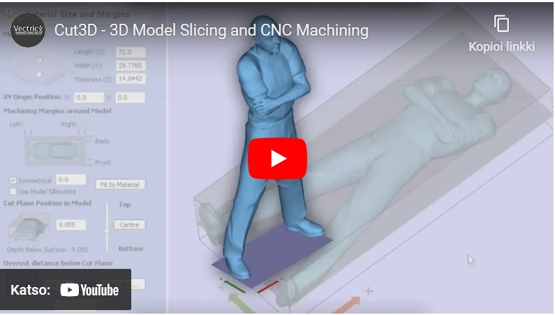
3D-mallit, jotka ovat liian suuria/paksuja koneistettavaksi portaalin korkeuden, leikkurin pituuden tai rajoitetun materiaalin paksuuden vuoksi, voidaan leikata erillisiin osiin. Jokainen viipale voidaan sitten työstää ja koko työ koota.
Cut3D is a dedicated toolpath engine for CNC machining 3D models that have been designed using a 3D CAD or Graphics design product such as AutoCAD, Rhino3D, 3D Studio etc. or scanned using a laser or touch probe device. Cut3D's exceptionally easy to use interface leads you step-by-step through the process of loading a model, setting the size, interactively placing tabs to hold the job in place, calculating single, double or four sided roughing and finishing toolpaths, previewing the results and finally saving the CNC code to run on your machine.
3D Models that are too large / thick to machine because of gantry height, cutter length or limited material thickness can be 'Sliced' into separate pieces. Each slice can then be machined and the complete job assembled.
3D Model Formats
Cut3D includes powerful import filters that work with most of the industry standard mesh file formats. 3D CAD and Graphics Design software packages will typically include standard options for saving 3D models in at least one of the file formats supported by Cut3D. The commonly used design software products are, Rhino3D 3D Studio AutoCAD Bobcad ProEngineer Solid Works SolidEdge Silo The internet is a very useful source for 3D models with many web sites offering 3D clipart pieces. Many of these also offer Free models that can be used to test they work with Cut3D.
The 3D file types supported in Cut3D are STL, 3DS, DXF, OBJ, SBP, TXT, WRL, X, LWO, V3M
Estimated Machining Times
Cut3D automatically calculates the theoretical cutting times for each of the toolpaths using the specified feed rates. A scaling factor can be used to improve the accuracy of the estimated timings when cutting 3D toolpaths. This is often needed because the CNC equipment may not achieve the programmed feed rates when running in 3D mode.
Saving the Toolpaths
Standard postprocessors are included for virtually all CNC machine control systems. The postprocessors are 'open' and can easily be configured to match specific file formats. The postprocessor supports Automatic Tool Changing and can easily be modified to save the roughing, finishing and cut out toolpaths into a single file.
Sizing and Positioning
3D Models are typically designed in any orientation and at any size. Cut3D includes options for selecting what faces of the model to machine, mirroring, rotating and setting the required size in Inches or Metric.
The maximum size a model can be machined is often limited by the available material thickness. Cut3D includes options to scale a 3D model proportionally or each axis independently, allowing the Z thickness to be scaled for the material size.
Multi-sided Machining
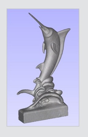
3D models can be machined as single, double or four sided projects. Simply select the option required and Cut3D calculates the all of the associated toolpaths automatically!
This approach allows 3D models to be machined on conventional 3 axis CNC machines.
For example, when selecting to machine a model on 2 sides Cut3D automatically calculates roughing and finishing toolpaths for the Top and Bottom halves of the design.

Automatic Boundary Detection with Tabs
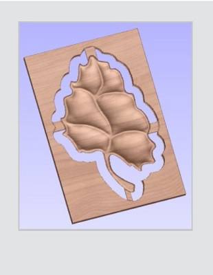
When cutting 3D projects it's important to minimize the machining times by not wasting time cutting unwanted regions of the material. Cut3D includes a unique option for detecting the model boundaries and limiting the toolpaths inside these regions.
This approach ensures the cutter doesn't waste time cutting a complete rectangular region, which is often the case with many other CAM products.
Interactive Tab Placement
When cutting models completely out of the material it's essential to have tabs to stop the job breaking free during machining.
Adding tabs to a model is very easy. Simply specify the required tab size and click on the model to snap a tab between the material edge and the model.

Fast and Efficient 3D Toolpath Options
Roughing Toolpaths
Fast and efficient Z level rough machining removes unwanted stock material quickly and easily, leaving material on the model for the finishing toolpath to remove.
The rough machining strategy includes options for profiling at each Z level to reduce uneven loading on the finishing cutter.
Finishing Toolpaths
High quality 3D finishing cutterpaths are calculated in seconds. Automatically compensating for the cutter diameter and ensuring gouge free parts off the CNC machine.
Cut Out Toolpath
Once the model has been machined to the required size it can easily be cut out of the material using the cut out toolpath. This option automatically calculates the boundary silhouette and calculates a multiple Z level profile toolpath to cut around the shape.
The cut out toolpath includes the options to preserve or cut through tabs if they have been added to the model.



Model Slicing
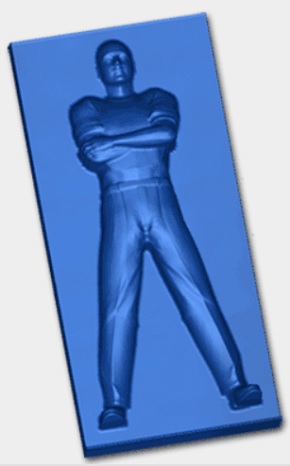
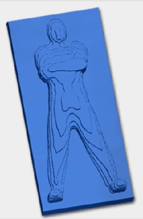
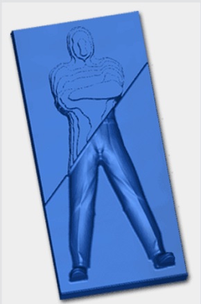
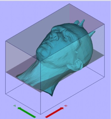
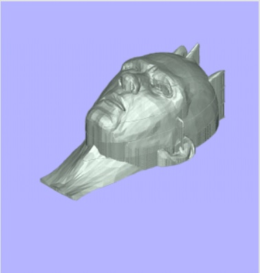
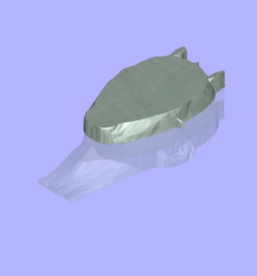
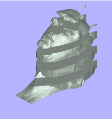
When a 3D model is too large / thick to fit under the gantry on your machine or you don't have thick enough material, the model can very easily be 'sliced' into thinner sections. For example, a 24" high model can be sliced into 12 x 2" thick pieces that can then be machined and assembled.
Cut3D automatically detects and machines the 3D edges of each piece of material, minimising the machining times by not cutting the flat region of the material. Tabs can also be placed on each slice to hold the design in the material during the machining process. The finish slices are assembled to make the full size project.




Realistic Toolpath Preview
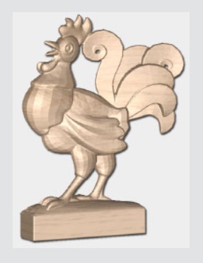
The calculated toolpaths can be simulated into different materials to show exactly what they will produce when run on the CNC machine.
Surface finish and level of detail the selected cutters will produce on the finished model can quickly be assessed before actually running the job on the machine.
The waste material surrounding a machined model can be deleted to display only the preview of the model.
High quality rendered images of the 3D preview can be saved and supplied to customers for job quotations and approval. These images are also prefect for web site content and marketing materials such as brochures and posters.

Ota yhteyttä
Ota yhteyttä ja kerro mitä lisätietoja haluat tästä tuotteesta
